In the second installment of the E30 suspension upgrade story I continued with the front axle. Besides the Bilstein Sport shock absorbers and the H&R OE Sport springs whose counterparts I had already installed in the rear, I also decided to replace the control arms and the control arm rubber bushings. Only that being lazy and not wanting to deal with removing the tightly fit old bushing and squeezing in the new one (stories go that this is pretty tough) I decided to buy new “lollipops” with the bushings already installed. On bavauto.com a new bushing costs $12.95 while the whole bracket goes for $49.95. A waste of money, I know, but what the hell - it was Christmas. The next time I surely won’t be spending so lavishly; I’ll probably just upgrade to urethane or M3 bushings which are more expensive anyway. I also replaced all the self-locking nuts during this procedure, as the manual recommends.
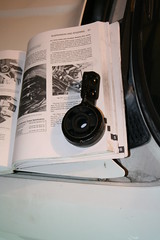
Click on pictures to see the exact location of the parts and components referred in this article. Click here to see the full set of pictures.
Start by loosening the wheel lug bolts, then
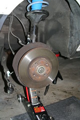
jack up the front of the car and put it on jack stands. In the course of those few days of work I noticed that my floor jack has started to slip – it slowly loses pressure and gives way. That’s not a good sign; I need to replace it although it’s only a couple of years old – how long are those things supposed to last anyway? Besides, it’s still too low at maximum extension (13”); this is more noticeable in the front – with the car elevated there’s still barely any place to move around under it... Remove the front wheels. Disconnect the ABS sensor wire from the hook on the strut housing and unscrew the ABS sensor from the spindle (5mm hex wrench). On the left side, disconnect the brake lining sensor.
Remove the
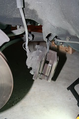
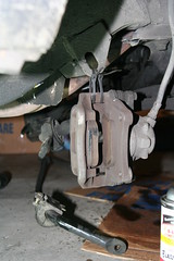
brake caliper mounting bolts and slide the caliper off the rotor. Attach the caliper to the car body to avoid damaging the flexible brake hose. Do not let the caliper hang on the hose. I used zip-ties for this job – there’s an adequately placed hook in the wheel cavity.
Caliper attached with zip-ties
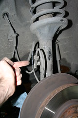
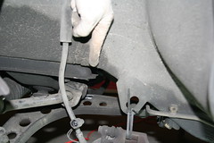
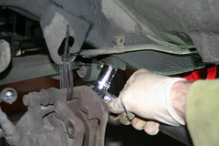
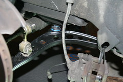
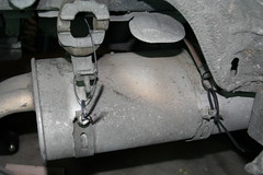
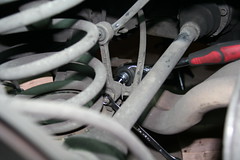
Disconnect sway bar connecting link
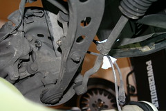
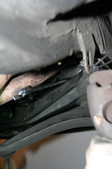
Broken subframe tab!
Disconnect the
stabilizer bar from the
connecting link (the piece that’s attached to the control arm at the other end). At this moment I realized that the subframe tab that the sway bar supporting bracket was attached to was broken – my sway bar was kept in place by the two connecting links and by the right-side bracket – the subframe tab on the passenger’s side was still intact. I searched a little on the forums and it turned out that this is a common problem and the only solution, barring the replacement of the subframe, is welding. That sounds like a job for Boris, the Russian body mechanic that fixed my Jeep a few years back when I parked like an idiot and hit a garage pole.
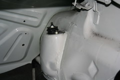
Before disconnecting the lower ball-joints, give a tug to the
nut on the top of the shock absorber rod, just enough to loosen it. This trick, courtesy of
http://zoso.no-ip.org, will make the removal of the nut easier when the time comes (otherwise the rod would turn on its axis). Do not remove the top nut at this time – as long as the spring is not compressed and pressure is still exerted on the shock mount, this would be very dangerous. I sprinkled the gland nut with PB Blaster penetrating catalyst, just in case the threads had seized, and let it soak overnight.
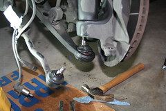
Tie rod and control arm ball joints removed
Remove the
tie-rod ball joint and the
control arm ball joint from the strut housing. This was no walk in the park; the ball joint rods were stuck in their holes and I had to use pickle forks and a lot of force to release them. Maybe some PB blaster would have helped but I got so riled-up that I solved the problem by using a lot of muscle and I even hit the rods with a hammer until the darn things came out. I was gentle with the tie rod, which I was going to reuse, but I went berserk on the control arm joint. Despite all precautions I tore a cut in the tie rod protective rubber boot with the pickle fork. I see a tie-rod job in the future, just so that the suspension overhaul becomes complete...
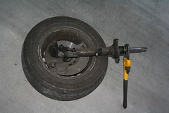
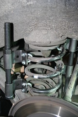
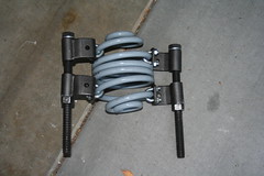
After disconnecting the three self-locking nuts from the shock tower I removed the strut, laid it on the floor and proceeded to
compress the spring. By now, after using that compressor on eight springs (rear and front, 4 old, 4 new) I hate the thing passionately. It takes too much work, sweat and time to compress and release those coils. It bends and jams and I have to hit it sometimes with a mallet to re-adjust the clamping brackets. Luckily I don’t intend to do this again anytime soon. When the spring was compressed I removed the top rod nut, which was already loosened. I had to clamp the rod through the coils with a small pipe wrench while I unscrewed the nut. The original rubber shock absorber stop came out completely destroyed.
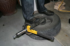
Removing the gland nut that holds the shock in the strut housing was a different story... To do this by yourself you need enough leverage; you have to hold the strut in place while you clamp a pipe wrench around the gland nut and twist it. I didn’t have vise grips or any other locking mechanism and my left arm just wasn’t strong enough. Superpowers would have been welcome; by that time I was already beat tired. I remembered that someone on
bimmerforums.com had suggested in an older thread that the strut be put back in the wheel during this procedure. That’s what I did, and I loosely attached it with two lug bolts. I stood on the wheel holding the strut housing under my foot while I clamped a large pipe wrench around the gland nut and turned – the nut came loose at the first tug. I lifted the bottom of the strut up a bit and hoisted it on some blocks of wood to let the oil drain out, and moved on to the control arms.
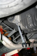
Disconnect the control arm from the frame
Disconnect the control arm
rubber bushing bracket (aka "
lollipop") from the frame. That’s no big deal; they’re held by two easily accessible bolts. The outer ball joint was already free, so that left the inner ball joint nut as the last point of attachment.
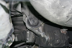
Sway bar removed
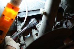
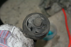
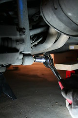
Control arm
inner ball joint nut
The inner ball joint nut was a major pain to remove. It’s not easily accessible and barely visible from under the car, so you have to feel your way around it. My socket didn’t fit in that place because there is a metal block behind the nut, too close to it to let the socket fit. Which left a the job to a regular wrench, but..., surprise-surprise, that’s a 22mm nut and I had no wrench that size (only the useless socket). During the subsequent late-evening trip to Schuck’s I found out that
22mm was not a standard size included in any of the metric wrench sets that were on the stands for sale. Luckily they sell one individually for a few bucks. Not a ratcheting wrench, a simple one, mind you. It took forever to unscrew that nut; loosening it cost me a good bruise on my hand when it finally popped. The passenger’s side is even more evil – the exhaust is in the way, and so is a small heat shield meant to protect the control arm rubber bushing from the heat of the exhaust. There is no place to wield a wrench in there, thus I ended up removing the stabilizer bar bracket and the heat shield to get a couple of inches of clearance so I could move the wrench. The nut finally gave up and surrendered. The disassembly phase was over.
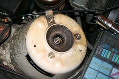
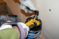
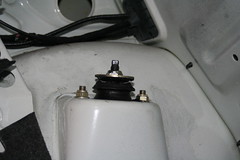
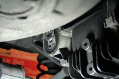
Tighten the Bilstein gland nut
I began the installation phase by locking in the
shocks inside the strut housings. Before you screw in the gland nut, don’t forget to place the white plastic ring that comes with the Bilsteins on the housing. This ring will hold the blue rubber boot that protects the piston rod from dust. To screw in the new gland nut I asked a friend to sit on the wheel and hold the strut in place under his foot while I operated the big pipe wrench. It dented the rim of the gland nut a bit but it doesn’t really matter. Legend has it that Bilstein sells a collar tool that fits on the gland nut, which you can attach a ratchet to. The tool doesn’t come with the shocks and you can’t order it from Bavarian Autosport. Someone posted the Bilstein part number 420017 for this thing, but I couldn’t find any reference to it on their web site catalog. So I used the wrench and it did just fine. I didn’t use any Loctite for this, I hope they hold well.
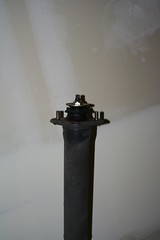
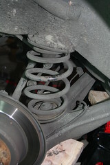
For the re-assembly of the strut I compressed the new H&R spring, and then I installed the
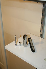
new shock mount, reusing the rubber ring, the top spring retainer, and the washers, finally proceeding to tighten the top nut, with the compressor still attached. The tightening should be easy – you can put a 19mm wrench around the nut while you hold the hex-shaped top of the rod with an 8mm wrench. However due to a historic design accident, not limited to German engineering, the top rod nut goes inside the central cavity of the shock mount where it can't be easily reached. After some thinking and asking around I had to invent my own tool: a small 8mm socket, ¼” drive goes inside a large, deep 19mm socket, ½” drive. A 3”-long, ¼” drive extension is attached to the 8mm socket at one end, while the other end goes through the ½” opening of the larger socket and connects to a ratchet.
The magic strut tool in action
Holding the ratchet with one hand, clamp a pipe wrench around the 19mm socket and
tighten. It’s still not perfect because of the need to use the pipe wrench, but there was no other practical alternative. I would have preferred a ¾” spark plug socket – the opening is exactly 19mm and fits the nut, while the top is hex-shaped and would fit a regular wrench. Unfortunately the top opening of those sockets is not large enough to allow for the ¼”-drive extension to pass through. Anyway, the resulting combination did the job perfectly. Some people have ridiculed it on the forums, proposing an
impact wrench instead. That may have worked just as well but for three significant disadvantages:
1) Bilstein recommends against using impact wrenches with the top nut (big warning on the shock installation papers)
2) I would have had to mount the shock on the car with the spring compressor attached and remove the damn’ thing after the fact. There was not guarantee that the spring compressors were in the right position to make sure they would fit in the wheel cavity and would not be in the way instead.
3) Good impact wrenches cost big bucks and aren’t essential equipment for an amateur weekend mechanic.
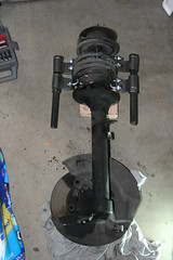
I put the
strut back in the car, supporting it with the jack; the assembly is quite heavy and doesn’t make it easier for you if you’re trying to hold it in position with one hand while attaching the three top nuts inside the engine bay with the other. You’ll need either a helper or the jack. Since asking the wife was out of the question... I attached the tie rod once the shock mounts were secured.
Next it was the turn of the
new control arms. To squeeze the lollipop on the end of the arm I lubed the rubber hole (lubed, rubber, hole... get it?) with some dishwasher detergent (which would evaporate in a short time leaving the joint tight) and pushed. With some force the arm end slid through. At this point the Bentley tells you to attach the control arms back as soon as possible and lower the car on the floor so that the control arms can settle inside the new bushings. I took them at face value and the rest of the procedure was a sort of race against time (oh my god, omg, what would happen if I take too long???).
The first thing was to tighten the
inner ball joint nut, which was predictably a pain in the butt, as the removal had been. Then I screwed in the two bolts that hold the lollipops to the frame, and finally the
outer ball joint nuts. As I was done with both arms I realized that the
sway bar was still lying on the floor and it looked like it wouldn’t be the easiest thing to place it above the control arms. I tried unsuccessfully for a few minutes, but it was like trying to figure out a solution to Rubik’s cube – you’d figure out one side, but the other would come undone – then I gave up and detached one of the control arm bushing brackets. Sway bar in, lollipop tightened, brackets attached, calipers on, wheels on, go! I torqued all nuts to spec except for the two on the subframe. Those gave me enough grief just trying to fit them to their places – there was no way a torque wrench could have fit in there.
Timeline:
- Friday night – get a head start – jacked up car, removed wheels, detached sensors, removed brake calipers
- Saturday – removed struts, compressed springs, removed old shocks and springs, removed control arms and sway bar, installed new shocks in strut housings, went drinking
- Due to the last item on Saturday’s list, I woke up on Sunday with a hangover and no will to get dirty and do physical work, so I dragged it and made plans for the next day
- Monday I took the bus to work. That evening I bought parts for the makeshift strut tool, installed the shock mounts, and removed the spring compressors
- Tuesday evening – installed the struts, attached the tie rods
- Wednesday evening – control arms, done
.
I certainly learned a few things – I didn’t really have to change the control arms; the old ones looked good enough. But what the hell! ... In retrospect I bit more than an amateur like me could chew in one weekend. I’d recommend doing this in stages – one weekend the shocks and springs, the next the control arms, then the tie rods. Drinking on Saturday night may delay results. Even a professional mechanic, doing this on his own time, having to deal with wife and kids and grocery shopping, might find this job too much for one straight shot.
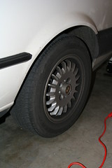
The
handling is much better now – adding to the improvements caused by the new rear suspension, there are a few noticeable changes. In curves the car always felt like it was going to keep moving ahead and the only thing that brought it to the course I was setting was the fact that it was still somehow attached to the wheels. Curves are now much more stable, the handling is reassuring. There was also a noticeable
front vibration propagated through the steering column at about 55-60mph, which I ascribed to the worn-out control arm bushings. That vibration is now gone. Other than that I’m left with a car that’s slightly lowered, (a bit less than 1 inch), a lot of bruises and I still feel like I’ve been working out lifting dumbbells for three days straight.
Click here to read more...
Summary only...