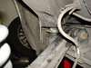
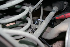
The rear axle carrier – also called cross-member or sub-frame – is attached to the chassis with a pair of sturdy bushings made of metal and rubber. Over time the rubber in these bushings weakens. Some bushings break, others merely sag. The overall effect is that the whole rear of the car feels a bit loose, as if it were moving sideways on its own when you turn. Shifting may result in a loud “clunk” when the clutch is pressed; momentum pushes the chassis forward while the final drive is suddenly decoupled; since the bushings are weak the subframe will jolt and bang against the chassis.
My car showed three different symptoms of mechanical failure in the drive train:
- A loud clunk when I shifted while accelerating, especially from first to second gear, louder when moving uphill – presumably caused by front-to-back play in the bushings. Let’s call this “the big clunk”. This one felt like the car was coming apart.
- A sudden bang when driving over certain small bumps or cracks in the road – probably caused by up-down bushing play that makes the subframe hit the supporting plate or the chassis
- A weak dangling sound when pressing the clutch, as if something were swinging side to side and banging against metal. Not sure what this sound is caused by. I can hear it even if the “big clunk” doesn’t occur. Let’s call this the “little clunk”.
Click on each picture to see a larger version and access the image notes. Click here for the whole set (contains some additional photos not included in this article).
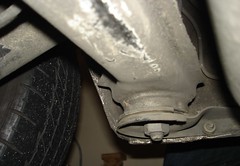
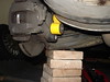
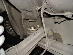
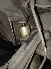
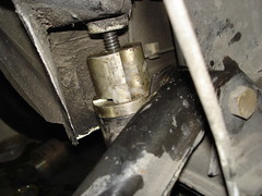
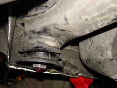
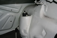
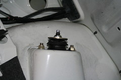
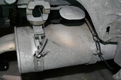
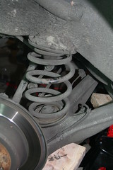
A good indication of the condition of the bushings is the gap between the cross-member and the support plate. If the bushing bottom touches the support plate, the bushing is worn out. The rubber that holds the bushing’s central hollow rod anchored to the outer sleeve weakens, making the subframe sag.
Preparation
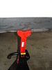
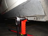
Normally I raise the rear and place the jack stands under the crossmember. Since you will be lowering the crossmember, the jack stands have to go somewhere else - the jacking point is right in front of the subframe support plate. The standard jack stands fit there, but the body rests on them in a rather precarious position. Maybe this support point is meant to work with a special BMW stand or a lift, neither of which can be found in my tiny garage.
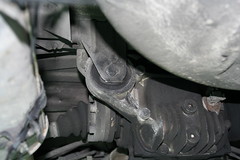
The exhaust pipe is merely an inch or so under the subframe. Release the support brackets that hold the muffler and lower the exhaust to make place for the subframe. I am not sure this step helped at all.
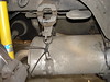
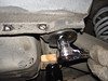
To create more space below the subframe, unhook the differential from its support bracket and lower the final drive (which is attached to the subframe with bolts). You should support it with a jack or blocks of wood. I forgot to support it for some time but luckily no damage occurred.
I thought that by lowering the trailing arm I would gain some additional space for the subframe, so I unscrewed and removed the shock absorber bolt. In retrospect this turned out to be unnecessary. I did not do the same on the right side and the subframe dropped just fine. Support the trailing arm if you chose to go through with this step.
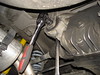
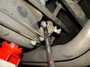
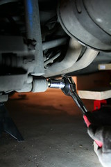
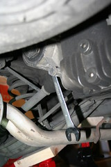
Give a good tug with a large wrench or breaker bar to the 22mm nut on the subframe bolt to loosen it. I had to use my large torque wrench for this; the nut wouldn’t budge with the regular ratcheting wrench. Support the subframe with a floor jack. Remove the 6mm Allen bolts that hold the support plate to the chassis. They come out easy, together with the reinforcement piece.
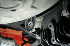
Remove the subframe nut and the support plate.
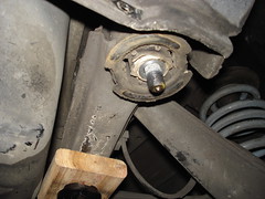
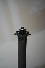
The rubber insides of the bushing look quite worn. Start banging on the bolt with a mallet or a hammer until it slides up the shaft. This part wasn't easy; it took a lot of hitting, sweating and cursing. There wasn't much space between the bottom of the car and the garage floor so I couldn't take a wide swing at it. It finally budged a tiny bit, then a little more until finally I was able to push it out with a screwdriver and the tap of a mallet. Some write-ups tell you to cover the top of the bolt inside the car with a towel so it doesn't fly against the ceiling when you hit it. This bolt never flew anywhere - it moved bit by bit with every blow.
Release the jack and lower the subframe. It didn't go down too far; I had to push and pull and fight for every inch.
There wasn’t enough space to squeeze the bushing tool between the subframe and the chassis, so I decided to unhook the stabilizer bar from the trailing arm to gain some additional room. In retrospect, just like with the shock, I am not convinced this step was necessary.
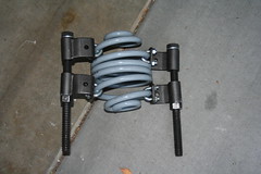
The tool
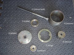
Subframe bushing tool parts
I bought the subframe bushing tool on eBay for $150. It seems to be part of a multi-model bushing tool kit code-named BMW2336, made by a manufacturing company called Sir Tools and sold by resellers like Zdmak and Technictool, for about $300. This kit is no longer for sale; it has been superseded by tool set BMW3026. The tool I bought is limited to the parts that are needed for the E30.
Since the parts did not come with instructions I emailed both Sir Tools and Zdmak asking for a courtesy copy (it was quite obvious how it worked, but nonetheless). Sir Tools answered a week later and actually sent me a copy by email.
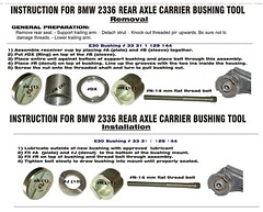
These are the tool directions as found on the internet. The removal steps are accurate but the installation instructions go against common sense. In order for the tool to push the bushing in the subframe when the bolt is tightened, the top piece (#R) must sit on top of the collar (#J) which sits on top of the subframe. The instructions say something else. They must have been written by someone who has never seen the underside of a car.
I could have tried to build a similar tool myself, but I just felt like spending the money this time (unexpected bonus at work helped too). Building a tool requires some pipe fittings and caps, a few nuts, a long threaded bolt and a bit of drilling. The sizes of pipe fittings must be carefully chosen to ensure they match the subframe cavity. You can find examples of home-made tools here and here.
Removal
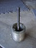
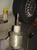
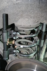
Place sleeve (B) over bottom plate (A) and ring (C) on top. Slide bolt through plate. Grease the threads well.
Tool in place for removal
View from the top
The ring pushes against the bottom of the subframe “cup” that holds the bushing. The bolt is threaded through the bushing and screwed onto the cap, which sits on top of the bushing.
The vertical notches in the “cap” must line up with the dimples in the subframe, otherwise the cap won't slide down when the bolt is tightened.
The ring is designed so that the metal collar at the bottom of the bushing can slide through it in the sleeve, while its two opposing protrusions push against the subframe.
The tool must be perfectly centered - if it's not, it may slip on one side and the ring bites through the subframe exterior coating - which is what happened to me. I re-centered the tool and it stayed in position this time.
The actual removal of the bushing only took a couple of minutes.
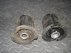
The inner metal cylinder of the old bushing is higher up in the sleeve than the new Lemforder bushing. This is because the rubber around it has weakened. This is probably the original 21-year-old bushing.
Installation
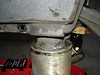
Tool set up for installation
View from the top
Set up the tool for installation. The top cap piece sits on the collar which rests on the subframe. The top of the bushing will pass through the collar and go into the cap. The slits at the bottom of the cap engage the tracks that jut out of the collar, so the cap doesn't move when the bolt is tightened. The threaded bolt must go through the chassis hole where the knurled bolt was; otherwise the bushing can't rise in the subframe cup.
The rubber is lubed with a very thin solution of water and dish soap. It evaporates almost instantaneously. The vertical groove in the bushing must be aligned with the dimples in the sleeve of the subframe.
Remove the tool. Raise the subframe. Don't forget to put the washer back on top of the bushing before raising the subframe.
To make the knurled bolt drop all the way down and lodge itself in the chassis I had to push and pull on the subframe to align the bushing with the hole in the chassis, I raised the sagging differential a bit, and then hammered away on the bolt head from inside the car. The hammering was needed because the last inch or so would not go down freely and when the nut was tightened the bolt would just turn on its axis. I couldn't find out if the nut was supposed to be a single-use self-locking nut, so I used some red Loctite and 120 foot-pound of torque. I found the number somewhere on the BFC forum; it may not be accurate, but the Bentley does not say anything about the subframe, so there...
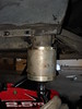
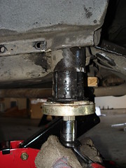
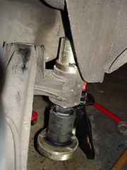
Notice the healthy gap between the support plate and the bushing. It will become smaller when the car is back on the ground.
Installing the right-side bushing
Now do the same thing on the passenger’s side. The subframe dropped much easier and lower than on the driver’s side without removing the shock absorber bolt. Actually, everything went easier on the passenger’s side: I didn’t have that much trouble removing the bolt (it moved after a few hits with the hammer) or putting it back in.
Cost
Tool: $150+shipping.
Parts: $45.50 for Lemfoerder bushings on Pelicanparts.com
Time & effort
Around 8 hours – I started at 9:30 AM; the car had its wheels back on the ground shortly before 6PM. This includes jacking up, a short trip to the auto parts store and lunch. Most of the time was spent ratcheting, banging on stuck bolts and in procedures that weren’t strictly necessary. The actual removal and installation of the bushings was a matter of minutes. I can’t imagine how long this procedure would have taken without the special tool. It’s one of the most complex procedures I have completed, albeit less complex than the front suspension upgrade. It was very demanding physically: that evening my hands and forearms were so sore and swollen I could barely turn a door knob. Lifting the glass of beer to my mouth was painful. I hurt until the following Tuesday.
Effects
I drove for a few days on steep Seattle streets full of potholes before posting this. I can confidently say that clunk #1, “the big clunk,” is gone. Going over bumps and cracks feels more solid now as well – I don’t get the impression anymore that the rear of the car would fall apart, but this may be just wishful thinking – I have sport suspension, the ride is a bit rough anyway. Clunk #3 is still there, though. Now with the subframe bushings out of the way I can only ascribe it to the differential dangling in the center support bearing. Or something. The quality of ride has definitely improved, but not dramatically.
Conclusion
Do it. If you get “the big clunk” changing the bushings will result in a clear improvement to your shifting. If you decide to do it the barbaric way – removing the subframe entirely, cutting through the bushing with a saw, burning the rubber, taking the cross-member to a mechanical shop to have the bushings pressed in, doing whatever you need to do - it could take much longer, depending on your experience and whether you're working alone or with a helper. Things have been done that way many times and you will find a few write-ups online to guide you. To each his own.
Click here to read more...
Summary only...