Run the equator

Monday, November 15, 2010

Troubleshooting the charging system

On a Thursday evening the dash indicator lights started flickering while I was braking. The next day, as I was driving home, the radio started going in and out, and the blinkers were having a hard time clicking, the dash lights faded; the car became plagued by a host of electrical issues in a short time. I had just pulled off the highway in a residential street and the car died suddenly; no sputtering, no jerking, the engine just shut off.

I came back two hours later and – surprise! – I was able to start the car and drive (without headlights, to conserve the battery charge) the few remaining blocks to my house where it died again, just as I pulled into the garage.

Considering that the car had shut off while driving, when the alternator should supply all power, and that it started later again on battery alone, I was pretty certain this was an alternator problem not a battery problem.

The question was how to I tell whether this was caused a broken alternator or a broken voltage regulator. The two components work together: the alternator produces the current that powers the car and recharges the battery when the engine runs, while the voltage regulator controls the field current that activates the electromagnets located on the rotor inside the alternator. If the alternator fails there is no current to power the car’s electric components and recharge the battery. If the voltage regulator breaks, it may fail to limit the current generated by the alternator and melt the battery or it won’t apply current to the rotor’s electromagnets, which in turn won’t generate current when the rotor spins (the beauty of 10th grade physics…) Many things can go wrong with this system. Here’s a link to a more detailed technical description: http://www.familycar.com/Classroom/charging.htm

Tests that indicate which component has failed exist but you’d have to start with a fully charged battery, and mine was dead (it measured 11.3V, which is as good as dead). The flickering of the dash lights usually indicates that the brushes of the voltage regulator, which supply the current that magnetizes the alternator rotor on contact with the rotor’s slip rings, have worn out and make intermittent contact. Replacing the voltage regulator is an easy job on the Bosch alternators used in E30 cars; the VR is mounted on the back of the alternator with two screws. The regulator can be replaced without removing the alternator. The battery must be disconnected first.

I decided to replace the voltage regulator and assumed the alternator was still good; it was unlikely that both would fail at the same time. Besides, the VR is much easier to replace that the alternator and cheaper too: only $20 at PelicanPart.com, whereas a rebuilt alternator can cost up to $200.

It turned out my assumption was correct; the voltage regulator brushes had worn down. The brushes were 3 and 4 mm in length, respectively; the shorter of them was covered with black soot. The VR should be replaced when the brushes are down to 5mm length.

Here’s a photo of the new and old parts, side by side.

My alternator may not be feeling very well either. I checked the voltage at the battery while the engine was revved up to 1500 RPM and it didn’t exceed 13.6V; it should go up to 14.5V. This is probably a sign that one of the alternator’s internal circuits is broken or burned; the whole thing is getting close to the end of its useful life. Here’s a new project to think of soon.

Click here to read more...

Saturday, September 25, 2010

Front Subframe and Oil Pan Gasket

The oil pan has been leaking for a long time, leaving clusters of dark spots on my garage floor. Sooner or later I had to replace the oil pan gasket, so I bought a new one. That was a year ago. In the meanwhile I read about the procedure on books, web sites and forums. The more I read, the more I realized this was going to be a tough job. The oil pan on the M20 engine is difficult to remove without doing a lot of additional work like removing the subframe or raising the engine. Because of limited clearance you may need to drop the oil pump in the pan before being able to remove the pan; then you would have to mount it back on with the pan around it. Not an encouraging prospect. Finally the opportunity presented itself to take on a bold goal: I had decided to replace the front subframe as well because one of the tabs that the stabilizer bar attaches to was broken, causing a very annoying rattle when the stabilizer bar banged against the subframe.

I didn’t have to buy a new subframe for this, but at that moment I felt that instead of looking for someone who could weld a new custom tab to it, I would rather buy a new one. I found a new subframe on eBay, sold by a family dealership that was trying to get rid of some stock parts for past models and negotiated it to $350. By comparison Bavarian Auto sells one for $541.95. A waste of money anyway, you will say. Yes, disposable income leads to unjustified expenses.

The decision was easier now: I had a justification to remove the subframe so I didn’t have to remove the oil pan the hard way. In the process I would not only fix the leak, but also stop the stabilizer bar rattle. To remove the subframe I had to support the engine from above, so I bought an engine support bar from Harbor Freight for $50. I decided to replace the oil pump as well. I haven’t heard reports of oil pumps breaking, but this was an opportunity to make sure everything in the oil pan was new. I certainly wasn’t going to enjoy repeating this procedure if the pump ever needed replacement.

Click here for the full set of pictures. Click on thumbnails for a bigger version, with notes that indicate the location of various components.

Preparation (Day 1, Wednesday)

As usual, start with raising the front and removing the front wheels.

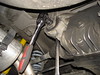
Remove the 17mm bolts that secure the control arm “lollipop” bracket to the body.

Remove the 13mm bolts and release the brackets that hold the stabilizer bar to the subframe (the bar will now be resting on the control arms). I only had one of those left, on the passenger’s side. The one on the driver’s side was missing.

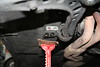
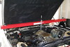
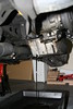
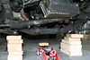
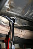
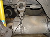
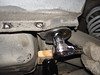
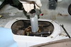
Install engine support bar above engine; hook it to support loop bracket.

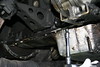
Remove the oil protective plate for better visibility under the engine and access to the oil pan. The plate is held by some metal screws and plastic fasteners.

Remove oil drain plug and drain oil overnight. Remove oil filter. In fact I should have drained the oil before raising the car, because some oil collected at the rear end of the pan and came out pouring on the floor when I removed the pan later.

Remove the front subframe (Day 2, Thursday)

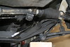
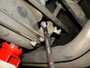
Detach the steering rack from subframe by removing the two 15mm bolts. You will need replacement self-locking nuts. Move the steering rack out of the way.

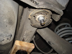
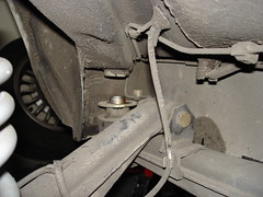
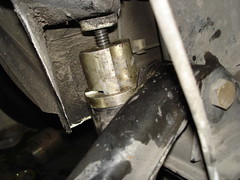
Remove the 17mm nuts that hold the motor mounts to subframe. Lift the engine just enough to make sure it’s securely attached to the support bar.

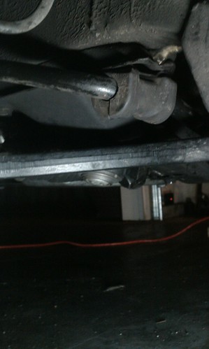
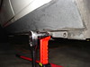
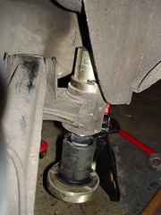
To prevent accidents, support the subframe with a jack before detaching it. Then remove the 4 17mm retaining bolts and lower the jack. You may need to hit the subframe with a hammer or mallet if it’s stuck to the chassis.

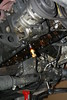
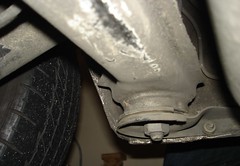
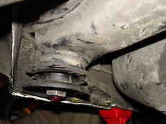
When I removed the subframe, the driver’s side motor mount fell, which it wasn’t supposed to happen. I realized that the rubber part had separated from the upper metal plate, which meant that the engine was just resting on the mount, susceptible to vibrations and shifts in position. This would not be enough to get the engine to fall off the mount, but enough to cause unpleasant vibrations and clunking. Unfortunately I had not planned to replace the mounts so I had to order them and wait over the weekend.

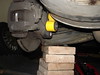
Support control arms after dropping the subframe, so the strut mounts and tie rods won’t have to bear all the weight.

Remove the 22mm nuts that hold the control arm ball joints to the subframe. This is difficult to do with the subframe in place because the space is very limited. Removing the nut was much easier after the subframe was dropped. Take the subframe out of the way – I had to hit the ball joint bolts with a hammer to get them unstuck; be careful not to damage the threads.

Remove the oil pan (Day 3, Friday)

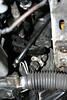
Disconnect oil level sensor connector (at the base of the alternator), remove dip stick. Remove the ground wire attached to the oil pan (I should have done this when I removed the sensor but I missed it; it was much harder to remove from the detached pan)


Remove 4 hex-head bolts (13mm) and the 5 Torx bolts (one E14, the others E12) that secure the bellhousing plate cover; remove the cover. Bentley says there are 4 Torx bolts; in reality there are 5 on mine, the leftmost bolt was very hard to remove. Make a note of the positions of the various bolts – they have different lengths.

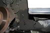
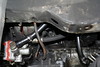
Remove the 25 10mm retaining bolts that hold the oil pan to the engine block. There should be enough clearance now, with the subframe removed, to move the oil pan out of the way before dropping the pump. Oil will flow!

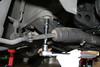
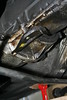
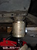
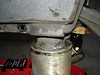
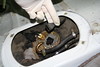
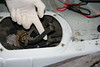
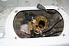
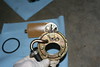
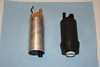
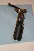
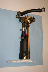
Remove the three mounting bolts and drop the oil pump - more oil will flow.

Scrape off the rest of the gasket and clean mating surfaces.

Install oil pan (Day 4, Saturday)

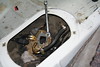
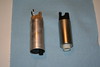
Install new oil pump, torque bolts to spec. (all torque values taken from the Bentley)

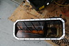
Install new gasket (I had a cork gasket), and place oil pan in position. This was a delicate operation. Once the pan fits you have to keep it in place with one hand while screwing in a few of the bolts with the other hand and make sure the whole thing does not shift. I used “Gasgacinch”, a sealant which I bought from O’reilly, on both mating surfaces. I had to shift the pan slightly once as some of the bolts wouldn’t fit, but fortunately it didn’t seem to drag the gasket too much around. There’s only one place where the gasket comes out about 1 mm.

Install all bolts in a star pattern, torque to 8 ft.lb. I think I may have applied more torque than necessary.

Install the bell-housing cover (no torque specified)

Re-attach ground wire and connect oil sensor connector.

Install oil drain plug and washer. Install new oil filter, put dipstick in Fill engine with oil.

Install subframe (Day 5, Tuesday)

I had to wait a couple of days for the new motor mounts to arrive.

Fit control arm center ball-joint bolts through the corresponding socket holes in the subframe; torque new self-locking nuts to spec. Keep control arms supported on wood blocks. I had to raise the subframe and prop it against the body, and then I pressed the ball joint from below with a jack because the ball joint on the right side was spinning around its axis when I tried to tighten the nut.

To be able to unlock the nut that secures the mount at the top to the engine support bracket I had to remove the brackets altogether. There was no easy way to get to that nut and wield a wrench in the limited space, especially on the passenger’s side where the charcoal canister hangs ½ inch above the nut. this could be avoided by removing the heat shield on the passenger's side and the charcoal canister on the driver's side.

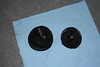
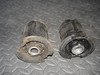
Remove the nuts and drop the mounts, or whatever's left of them - in my case the driver’s side mount was broken; the top plate had detached from the rubber part. Re-attach motor mounts brackets to the engine block.

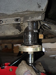
Attach the new mounts to the engine brackets, and tighten the top nut loosely. Raise subframe using a jack until it fits in position, the bolt guides match the bolt holes in the body, and the motor mounts and hood catch brackets fit the subframe's notches. I thought I needed a helper to wiggle the engine back and forth to fit the mounts, but this ended up being delicate incremental work: crank the jack one step, shove the subframe a bit, turn mounts to get them closer to the notches, push engine a tad to the left, repeat. Make sure you push the steering rack back in its location as you raise the subframe.

Bolt subframe on the body. No torque specified in the Bentley. Lower the engine completely; Remove engine support bar.

Tighten the motor mounts nuts, top and down. The top ones are difficult. I tightened them by hand as far as I could, then I used a 17mm short wrench to get them tight. No chance to tighten them to spec.

Attach steering rack to subframe, use new self-locking nuts.

Attach stabilizer bar to subframe. It wasn’t easy to attach the new bracket that had been missing before. I had to detach the link that connected it to the control arm first.

Bolt lollipops back on to chassis.
Wheels. Done.

The net effect: no leak so far, no oil drops on the garage floor.

Before replacing the broken motor mount I used to feel a strong vibration propagated through the steering column to the steering wheel at around 55-60mph. Changing the broken mount made this vibration go away.

Time

As you can see from the outline of this article I took my time. I was on vacation; I would wake up late, work for a few hours, then I'd take a break for the rest of the day. If I hadn't had to wait for the motor mounts to arrive the whole procedure would have taken less time. I believe you should be able to do this in one weekend, if you have all the parts and tools ready and you wake up early. It's hard work though; my back and hands would hurt after a few hours of constantly getting under the car and out again, and ratcheting with my hands in the air while lying down.

Cost

Not including various shipping charges

  • Subframe: $350
  • Motor mounts: 2x$52 = $104
  • Oil pan gasket: $8
  • Oil pump: $143.25
  • Various self-locking nuts: $10, maybe
  • Gasket sealant: $5
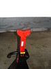
  • Engine support bar: $50
  • Small tools that I didn't already own: $15

Click here to read more...

Friday, March 12, 2010

The story of a rattle

A few months ago my ’88 eta started making these rattling sounds when going over bumps. It seemed to come from somewhere in the rear drivetrain. Not all bumps would cause it, and not all the time. It was more likely to happen on certain stretches of road, or at particular turns on my daily commute. Sometimes I’d go over the nastiest cracks in the road and nothing would happen. The clunk didn’t become worse with time, but it was always there.

I started to investigate; a few times I jacked up the rear, got under the car and checked every moving part. Nothing dangled, no parts had any play when shaken; nothing would make that sound. I looked at the calipers, the brake hoses, the brake pads (rattling brake pads are not unheard of) but nothing budged. I adjusted the park brake shoes (I had to do it anyway since the hand brake had become weak) but that didn’t help either. I checked the springs and shocks and the shock mounts; they were ok. I stripped the interior bare, looking for some dangling parts. I started questioning my prior repair jobs… maybe I hadn’t put the sub-frame back properly when I changed the sub-frame bushings? Everything seemed fine.

Last weekend I decided to finally abandon the assumption that the rattle was coming from the rear. Sounds can be misleading, they echo through the chassis; what I would perceive as coming from the rear could as well be caused by something dangling in the front.

I looked at the front calipers, the tie rods, the control arms… nothing moved here either, sideways or vertically, more than expected. Then, as I looked at the sway bar it all became suddenly clear.

A few months ago, when I worked on the front suspension, I noticed that the small pierced tab at the end of the sub-frame, which anchors the bracket that holds the sway bar, was broken and missing on the left side. The support bracket was gone too. The thick rubber piece was still around the bar, resting against the sub-frame. It looked nasty, but nothing that needed to be addressed immediately. That same rubber piece had shifted and the sway bar was resting against the bare metal of the cross-member. That’s what caused the rattle. Normally, the sway bar and the sub-frame would touch, but when driving over certain bumpy stretches or on grooved pavement, the wheel would move up and down, pulling the sway bar which is attached to the spindle with a link. Sometimes this movement would make the bar hit against the sub-frame. Rattle on!

I pushed the rubber piece back in its place, between the sub-frame and the sway bar, and I haven’t heard the rattle since. That’s a temporary solution; it’s about time to spend money and time for an actual repair job. Since I have to remove the sub-frame, I may as well do some other jobs there… like changing that leaky oil pan gasket.

At least I won’t be obsessing over this one anymore.

Bonus chatter: a new subframe costs about $500.

Click here to read more...

Thursday, December 17, 2009

Replacement of the BMW E30 rear subframe bushings

The rear axle carrier – also called cross-member or sub-frame – is attached to the chassis with a pair of sturdy bushings made of metal and rubber. Over time the rubber in these bushings weakens. Some bushings break, others merely sag. The overall effect is that the whole rear of the car feels a bit loose, as if it were moving sideways on its own when you turn. Shifting may result in a loud “clunk” when the clutch is pressed; momentum pushes the chassis forward while the final drive is suddenly decoupled; since the bushings are weak the subframe will jolt and bang against the chassis.

My car showed three different symptoms of mechanical failure in the drive train:

  • A loud clunk when I shifted while accelerating, especially from first to second gear, louder when moving uphill – presumably caused by front-to-back play in the bushings. Let’s call this “the big clunk”. This one felt like the car was coming apart.
  • A sudden bang when driving over certain small bumps or cracks in the road – probably caused by up-down bushing play that makes the subframe hit the supporting plate or the chassis
  • A weak dangling sound when pressing the clutch, as if something were swinging side to side and banging against metal. Not sure what this sound is caused by. I can hear it even if the “big clunk” doesn’t occur. Let’s call this the “little clunk”.

Click on each picture to see a larger version and access the image notes. Click here for the whole set (contains some additional photos not included in this article).

Sagging subframe
A good indication of the condition of the bushings is the gap between the cross-member and the support plate. If the bushing bottom touches the support plate, the bushing is worn out. The rubber that holds the bushing’s central hollow rod anchored to the outer sleeve weakens, making the subframe sag.

Preparation

Normally I raise the rear and place the jack stands under the crossmember. Since you will be lowering the crossmember, the jack stands have to go somewhere else - the jacking point is right in front of the subframe support plate. The standard jack stands fit there, but the body rests on them in a rather precarious position. Maybe this support point is meant to work with a special BMW stand or a lift, neither of which can be found in my tiny garage.

The exhaust pipe is merely an inch or so under the subframe. Release the support brackets that hold the muffler and lower the exhaust to make place for the subframe. I am not sure this step helped at all.

To create more space below the subframe, unhook the differential from its support bracket and lower the final drive (which is attached to the subframe with bolts). You should support it with a jack or blocks of wood. I forgot to support it for some time but luckily no damage occurred.

I thought that by lowering the trailing arm I would gain some additional space for the subframe, so I unscrewed and removed the shock absorber bolt. In retrospect this turned out to be unnecessary. I did not do the same on the right side and the subframe dropped just fine. Support the trailing arm if you chose to go through with this step.

Give a good tug with a large wrench or breaker bar to the 22mm nut on the subframe bolt to loosen it. I had to use my large torque wrench for this; the nut wouldn’t budge with the regular ratcheting wrench. Support the subframe with a floor jack. Remove the 6mm Allen bolts that hold the support plate to the chassis. They come out easy, together with the reinforcement piece.

Remove the subframe nut and the support plate.

Worn out bushing
The rubber insides of the bushing look quite worn. Start banging on the bolt with a mallet or a hammer until it slides up the shaft. This part wasn't easy; it took a lot of hitting, sweating and cursing. There wasn't much space between the bottom of the car and the garage floor so I couldn't take a wide swing at it. It finally budged a tiny bit, then a little more until finally I was able to push it out with a screwdriver and the tap of a mallet. Some write-ups tell you to cover the top of the bolt inside the car with a towel so it doesn't fly against the ceiling when you hit it. This bolt never flew anywhere - it moved bit by bit with every blow.

Subframe lowered
Release the jack and lower the subframe. It didn't go down too far; I had to push and pull and fight for every inch.

There wasn’t enough space to squeeze the bushing tool between the subframe and the chassis, so I decided to unhook the stabilizer bar from the trailing arm to gain some additional room. In retrospect, just like with the shock, I am not convinced this step was necessary.

The tool

Subframe bushing tool parts
I bought the subframe bushing tool on eBay for $150. It seems to be part of a multi-model bushing tool kit code-named BMW2336, made by a manufacturing company called Sir Tools and sold by resellers like Zdmak and Technictool, for about $300. This kit is no longer for sale; it has been superseded by tool set BMW3026. The tool I bought is limited to the parts that are needed for the E30.

Since the parts did not come with instructions I emailed both Sir Tools and Zdmak asking for a courtesy copy (it was quite obvious how it worked, but nonetheless). Sir Tools answered a week later and actually sent me a copy by email.

Instruction sheet
These are the tool directions as found on the internet. The removal steps are accurate but the installation instructions go against common sense. In order for the tool to push the bushing in the subframe when the bolt is tightened, the top piece (#R) must sit on top of the collar (#J) which sits on top of the subframe. The instructions say something else. They must have been written by someone who has never seen the underside of a car.

I could have tried to build a similar tool myself, but I just felt like spending the money this time (unexpected bonus at work helped too). Building a tool requires some pipe fittings and caps, a few nuts, a long threaded bolt and a bit of drilling. The sizes of pipe fittings must be carefully chosen to ensure they match the subframe cavity. You can find examples of home-made tools here and here.

Removal

Place sleeve (B) over bottom plate (A) and ring (C) on top. Slide bolt through plate. Grease the threads well.

Tool in place for removal
View from the top
The ring pushes against the bottom of the subframe “cup” that holds the bushing. The bolt is threaded through the bushing and screwed onto the cap, which sits on top of the bushing. The vertical notches in the “cap” must line up with the dimples in the subframe, otherwise the cap won't slide down when the bolt is tightened.

The ring is designed so that the metal collar at the bottom of the bushing can slide through it in the sleeve, while its two opposing protrusions push against the subframe.

The tool must be perfectly centered - if it's not, it may slip on one side and the ring bites through the subframe exterior coating - which is what happened to me. I re-centered the tool and it stayed in position this time.

The actual removal of the bushing only took a couple of minutes.

The inner metal cylinder of the old bushing is higher up in the sleeve than the new Lemforder bushing. This is because the rubber around it has weakened. This is probably the original 21-year-old bushing.

Installation

Tool set up for installation
View from the top
Set up the tool for installation. The top cap piece sits on the collar which rests on the subframe. The top of the bushing will pass through the collar and go into the cap. The slits at the bottom of the cap engage the tracks that jut out of the collar, so the cap doesn't move when the bolt is tightened. The threaded bolt must go through the chassis hole where the knurled bolt was; otherwise the bushing can't rise in the subframe cup.

Installation
The rubber is lubed with a very thin solution of water and dish soap. It evaporates almost instantaneously. The vertical groove in the bushing must be aligned with the dimples in the sleeve of the subframe.

Remove the tool. Raise the subframe. Don't forget to put the washer back on top of the bushing before raising the subframe.

Done!
To make the knurled bolt drop all the way down and lodge itself in the chassis I had to push and pull on the subframe to align the bushing with the hole in the chassis, I raised the sagging differential a bit, and then hammered away on the bolt head from inside the car. The hammering was needed because the last inch or so would not go down freely and when the nut was tightened the bolt would just turn on its axis. I couldn't find out if the nut was supposed to be a single-use self-locking nut, so I used some red Loctite and 120 foot-pound of torque. I found the number somewhere on the BFC forum; it may not be accurate, but the Bentley does not say anything about the subframe, so there...

Notice the healthy gap between the support plate and the bushing. It will become smaller when the car is back on the ground.

Installing the right-side bushing
Now do the same thing on the passenger’s side. The subframe dropped much easier and lower than on the driver’s side without removing the shock absorber bolt. Actually, everything went easier on the passenger’s side: I didn’t have that much trouble removing the bolt (it moved after a few hits with the hammer) or putting it back in.

Cost

Tool: $150+shipping.
Parts: $45.50 for Lemfoerder bushings on Pelicanparts.com

Time & effort

Around 8 hours – I started at 9:30 AM; the car had its wheels back on the ground shortly before 6PM. This includes jacking up, a short trip to the auto parts store and lunch. Most of the time was spent ratcheting, banging on stuck bolts and in procedures that weren’t strictly necessary. The actual removal and installation of the bushings was a matter of minutes. I can’t imagine how long this procedure would have taken without the special tool. It’s one of the most complex procedures I have completed, albeit less complex than the front suspension upgrade. It was very demanding physically: that evening my hands and forearms were so sore and swollen I could barely turn a door knob. Lifting the glass of beer to my mouth was painful. I hurt until the following Tuesday.

Effects

I drove for a few days on steep Seattle streets full of potholes before posting this. I can confidently say that clunk #1, “the big clunk,” is gone. Going over bumps and cracks feels more solid now as well – I don’t get the impression anymore that the rear of the car would fall apart, but this may be just wishful thinking – I have sport suspension, the ride is a bit rough anyway. Clunk #3 is still there, though. Now with the subframe bushings out of the way I can only ascribe it to the differential dangling in the center support bearing. Or something. The quality of ride has definitely improved, but not dramatically.

Conclusion

Do it. If you get “the big clunk” changing the bushings will result in a clear improvement to your shifting. If you decide to do it the barbaric way – removing the subframe entirely, cutting through the bushing with a saw, burning the rubber, taking the cross-member to a mechanical shop to have the bushings pressed in, doing whatever you need to do - it could take much longer, depending on your experience and whether you're working alone or with a helper. Things have been done that way many times and you will find a few write-ups online to guide you. To each his own.

Click here to read more...

Saturday, September 26, 2009

When your fuel pump goes...

I knew it had to happen to me sooner or later, and it did: as I left the grocery store heading home, my 21-year-old BMW did not start. A nice lady asked me if I needed help to jump the car, and I had to decline her offer; it wasn’t the battery, it had to be something else. Good thing the store was only a few blocks away from home. I had the car towed the next day, pushed it into my garage and started debugging.

There’s a straightforward step-by-step procedure you can follow to find the cause of a non-start. After eliminating the obvious suspects – a dead battery and the absence of spark – the most obvious component that needs to be tested is the fuel pump. In later E30 models (starting with production month 9/87) there is only a single fuel pump, located in the fuel tank, accessible through a hatch under the passenger’s side rear seat. It’s easy to check if the pump is working: remove the rear seat, remove the pump cover, crank up the car (or have a helper turn the key instead) and listen. The pump should make… well, pumping sounds, just as you imagine a fuel pump would sound. If you can’t hear anything it could mean that:

  1. Either the pump is broken and you need a new one, or
  2. You have no voltage at the pump – because either the wires are interrupted (pray that they aren’t because fixing wiring in a car is a terrible job) or your fuel pump relay is bad

To check for voltage remove the power connector from the pump, stick the probes of a voltmeter in the connector and crank the car – if the relay works the probe should show battery voltage, about 12V. Operating the ignition while holding the probe in the connector and reading the voltmeter display can be a pretty cumbersome task - another set of hands greatly helps. If you’re working alone you can simplify your life if you bypass the relay: remove it from its socket and link the connector’s pins 30 and 87 together with a wire (preferably a fuse holder with a 15amp fuse); this will bypass the ignition and supply constant battery power to the fuel pump (that’s also a good way to make sure the wiring is fine).

If there’s voltage at the fuel pump but the pump is silent it’s time for a new pump. There are a few models for sale that can fit the E30. The OEM pump for the ’88 E30 is a VDO. The good thing about it is that it comes with the complete assembly: fuel pump, mounting frame, filter and O-ring; you just swap the old one out and re-connect the hose. The average price online for this OEM part is about $200. The cheapest I could find it for was $176.35 at autohausaz.com. Unexpectedly, my usual supplier bavauto.com sells the VDO pump for an ungodly $362.95.

The TRE 340 in a box
The alternative is a pump from an aftermarket supplier like TRE or Walbro. The TRE 340 had good reviews (if you can ever take seriously anything you read on internet forums) and it’s for sale on eBay. The noticeable price difference ($78.98, shipping included) tipped the balance in its favor. However, generic aftermarket pumps come with a catch – they require some wiring work, and they may need modifications to the fuel pump assembly to fit.

This is the whole procedure, step by step. Click on each picture to see a larger version and access the image notes. Click here for the whole set.

The Bentley recommends disconnecting the battery (as it does for almost every procedure); I didn’t. Anyway, be careful when you work around fuel lines. Don’t smoke.

Remove the rear seat and then unscrew the four bolts that hold the black oval access cover on the passenger’s side. There’s a similar round cover on the driver’s side – that’s just a fuel gauge sending unit; leave it alone.

Remove the electrical connectors: the connector with 2 pins is the power supply. The other is the fuel gauge sender connector.

Loosen the hose clamp and remove the hose. Either end will do. The one on the fuel-line side was easier to remove. Fuel may be discharged – in my case there wasn’t any fuel in the line since the pump was broken.

Remove the four 8mm mounting screws on top of the fuel gauge sending unit.

Pull the sending unit out of the tank. Wait until all the liquid drips back in the tank. There is a lot of gas in the can, and it all drips out through a tiny hole at the bottom.

Rotate the fuel pump assembly counter-clockwise to loosen it.

Remove fuel pump assembly out of the tank. Make a note of the position of the assembly when it comes out. You will have to put it in the same way.

Look at the assembly and notice the alignment of the fuel filter relative to the frame. You will need to install the new filter in the same position.

Remove the filter by pulling on it, and then remove the pump from the frame. The connector wires are soldered to the assembly. You will have to melt the solder or cut the wires.


There’s an obvious size difference between the old pump and the new. Fit the sleeves that came in the package around the new pump - it will increase its diameter and make it fit snugly in the frame. The sleeves are optional.

The short feeding tube at the bottom of the TRE pump and the similar tube on the OEM pump have different diameters and are positioned differently. To make the new pump fit we have to tinker a bit with the assembly frame.


Carefully carve in the bottom support of the frame until the feeding tube of the new pump can fit through. Be mindful not to damage the frame too much. Either way, it’s not going to look pretty, but who cares – it goes in the tank!

Solder the connector wires that came in the package to the terminal pins on the frame. I wasn’t very good at that job. I hadn’t soldered anything since shop class in school. So far I’ve used butt connectors for all the electrical work on this car.

Use the short fuel hose (came with the package) to connect the pump’s outlet and the metal tube which is part of the assembly.

Pressing gently against the pump’s bottom tube install the filter maintaining the same orientation that the original filter had. I also strapped the pump to the frame with a zip-tie although it wasn’t strictly necessary; the pump was snug enough in place.

Insert the whole assembly with the new O-ring back in the tank. I couldn’t find an O-ring of the same size in any automotive shop and the local BMW dealer didn’t have one in stock so I decided to re-use the old O-ring. Let posterity judge me…

Reconnect and install the other pieces in the order they were disassembled.

Work time: about three hours.

After I completed the procedure, the car started immediately, as expected. I have not noticed any unpleasant noise when the pump is in operation. Now I can only hope that this new pump will last as long as the original one did...

Click here to read more...